
|
|
Output Transformers
Almost every type of vacuum tube amplifier needs an output transformer to match the high impedance of the output tubes to the low impedance of the loudspeaker load. When I started designing tube amplifiers, I found output transformers to be one of the hardest things to understand properly. There is plenty of information available on how vacuum tubes operate, but what I could readily find on transformers was rather general.
This leads me to believe that most amateur audio designers also have only a general knowledg of how transformers really work. After a bit of research, I am still no expert. Hopefully, I have learned enough to be useful to other amateur designers, though.
Some Basics
An output transformer is esentially two coils of wire wrapped around some magnetic core material. Placing an alternating voltage accross one of the coils of wire generates a magnetic field in the core which in turn generates voltage in the second coil. The voltage accross the second coil, secondary is equal to the voltage accross the first coil, primary devided by the ratio of the number of turns.
V2=V1/(N1/N2)
If you place a load accross the secondary, it will draw a current equal to V2/RL. The transformer isn't actually generating any power, so the current times voltage at both the secondary, and the primary must be equal. so I1=I2/(N1/N2). Using Ohms law and a little algebra, you can see that the resistance appearing accross the primary will be RL*(N1/N2)^2.
For example, suppose you have a transformer where N1/N2=20. The primary is connected to a vacuum tube that is generating an alternating voltage of 80v. The secondary voltage is 80/20 or 4 volts. If the secondary is connected to an 8ohm loudspeaker, the current is 4v/8ohms, or 0.5amps. That means the tube is supplying 0.5/20 amps or 0.025amps. So the tube sees a load of 80v/0.025 amps or 3200ohms. This gives the same result as 20^2*8.
That just about covers the basics, but it leaves a few questions. Why for instance, can't you just use a power transformer with the right turn ratio as an output transformer? Or, why won't a push pull transformer generally work as a single ended transformer. To understand that, I had to find out a bit more about magnetic fields. I found a lot of the answers by reviewing a couple of old Electronic Engineering text books.
Magnetic Flux.
This is a measure of the intensity of the magnetic field generated by current passing through a coil of wire. Flux density is related to the current flowing through the coil by the equation B=mu*H where H is I*N/p where I is current in amps, N is number of turns, and p is the average length of the magnetic path in meters. You can also solve flux density for voltage by the equation B=V/(4.44*f*Ac*N), where B is flux density in Teslas, V is the RMS voltage, f is the frequency of the voltage, and Ac is the area in square meters enclosed by the coil.
Air has such a low mu, that some magnetic material must be used to keep the magnetizing current low with a reasonably sized core. Unfortunately, most magnetic materials have a rather nonlinear magnetizing curve like the one shown below.
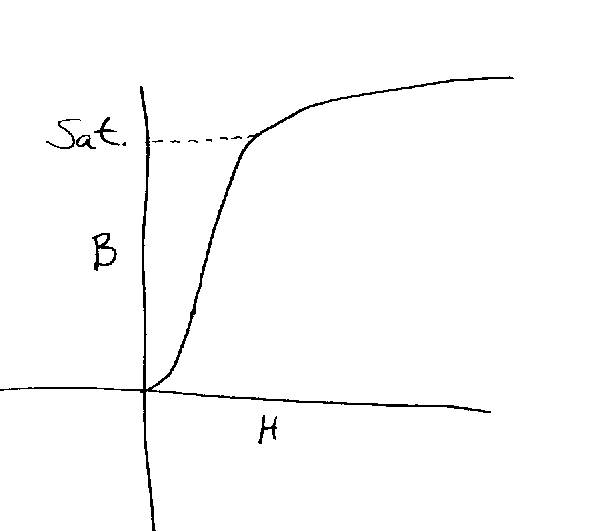
|
| artists rendition, may not be to scale |
If the magnetic material is driven beyond the saturation point marked on the graph, effeciency and linearity drop off dramatically. The designer will adjust the core area, and number of turns to keep the core from saturating at the rated output power and bass frequency. Power transformers are designed to saturate at the mains voltage and frequency of the power grid they are operating in. In the United States, that is usually 120v at 60Hz. If you wanted a transformer to go down to 20Hz, it would saturate at 40v RMS. That works out to 1/2 watts from a 3200ohm transformer.
Push pull transformers are designed to be biased at the origin of the curve shown above. Because of their hign inductance, it takes very little current to satruate the cores. Typical steel cores saturat when H is in the region of 200-300 amps*turns/meter. A typical 20 watt push pull transformer with 2500 turns on the primary, and a magnetic path of about 0.15 meter will reach 200 A*t/m with only 12ma of unbalanced current on the core. At 60ma bias, H is off the scale at 1000 A*t/M, and B can't go any higher no matter how much AC current you push through the core. In other words, if you try to use a push pull transformer in a single ended circuit, you are unlikely to get any power out, and what you do get will probably be noticably distorted.
|
|
|