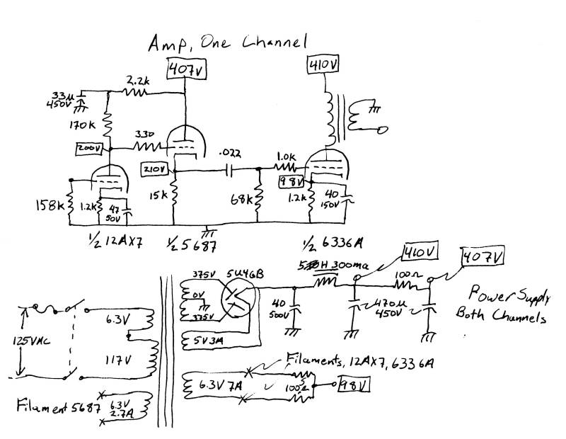
The 6336a turned out to be a rather challanging tube to design around. It has a much lower plate impedance than most other output triodes. Most amps use a load impedance 2-4 times the plate impedance. This amp has a load impedance about 10 times the plate impedance. Because of this, demands on the power supply are much greater than they would be with a more conventional tube. After some experimenting, I decoupled the first stage power supply from the output stage with a two stepRC filter. The first step was designed to damp the output stage power supply.
I also chose a bass cutoff frequency that is at least 1 octave above the natural full power cutoff of the output transformer. This allows the transformer to operat in a more linear range. (Yes, output transformers do add distortion to the amp). It also should reduce the demands made on the power supply.
I tried the amp with and without each of the features mentioned above. In the original circuit, all B+ was taken from the second capacitor in the CLC pi filter, with no decoupling. The cutoff frequency was also about an octave lower. Each change allowed the amp to be played noticably louder with less degredation of the sound.